The wiring
In a 1541tro, the floppy is connected directly to the monitor. This is done through the serial cable, which is normally meant to transfer data between the floppy to the C64.
The serial cable has three lines, but only two of them can be toggled on the floppy side (DATA and CLK).
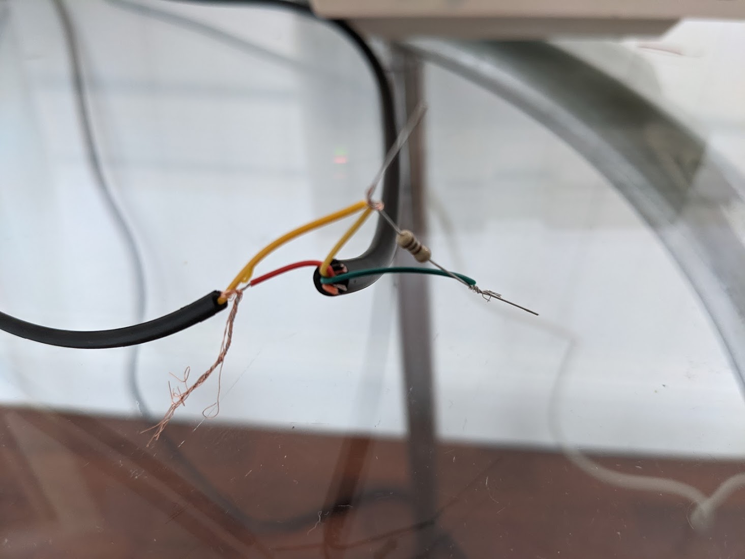
To connect the floppy to a monitor, the wiring we used is as such:

The "circuit" above is essentially a tiny D/A converter, enabling the floppy to generate three three voltage levels, by pulling DATA and CLK to 0V and +5V, respectively:
DATA CLK  VOLTAGE SIGNAL
------------------------
low  low  +0V     SYNC
high low  +0V     SYNC
low  high ~+0.5V  black
high high +5V     white
We need all three of these. Black and white for the graphics (yes, we only have two "colors"), and sync for both horizontal and vertical PAL sync pulses. (See this post from Martin Hinner for more about the PAL signal).
(Note that it's also possible to attach the resistor to the CLK line. It depends on which bit combinations in $1800 you'd like to use to generate SYNC and black levels.)
Here are the bit assignments for resistor at DATA (like in freespin). Note that signals get inverted on the 1541 board, so a "0" produces +5V.
DATA OUT | CLOCK OUT | ATNA OUT | Result
----------------------------------------
0        | 1         | 0        | Sync
1        | 1         | 0        | Sync
0        | 1         | 1        | Sync
1        | 1         | 1        | Sync
0        | 0         | 0        | White
1        | 0         | 0        | Black
0        | 0         | 1        | Black
1        | 0         | 1        | Black
Generating "pixels"
This wiring allows us to generate all the necessary voltage levels. But we still have to generate a valid signal. Every single raster line, we have generate sync pulse by pulling both DATA and CLK to ground for 5 - 8 μs. And of course, we have to switch back and fro between black and white. Since the 6502 runs at 1Mhz, a single CPU cycle is already 8 horizontal pixels. But writing 1800 takes 4 cycles, so every switch between white and black is always at least 32 pixels wide. This is perhaps the biggest restriction of 1541tros, and dictated most of the effects. (Oldschool effects, like rasterbars, chessboards etc. tend to work nicely)
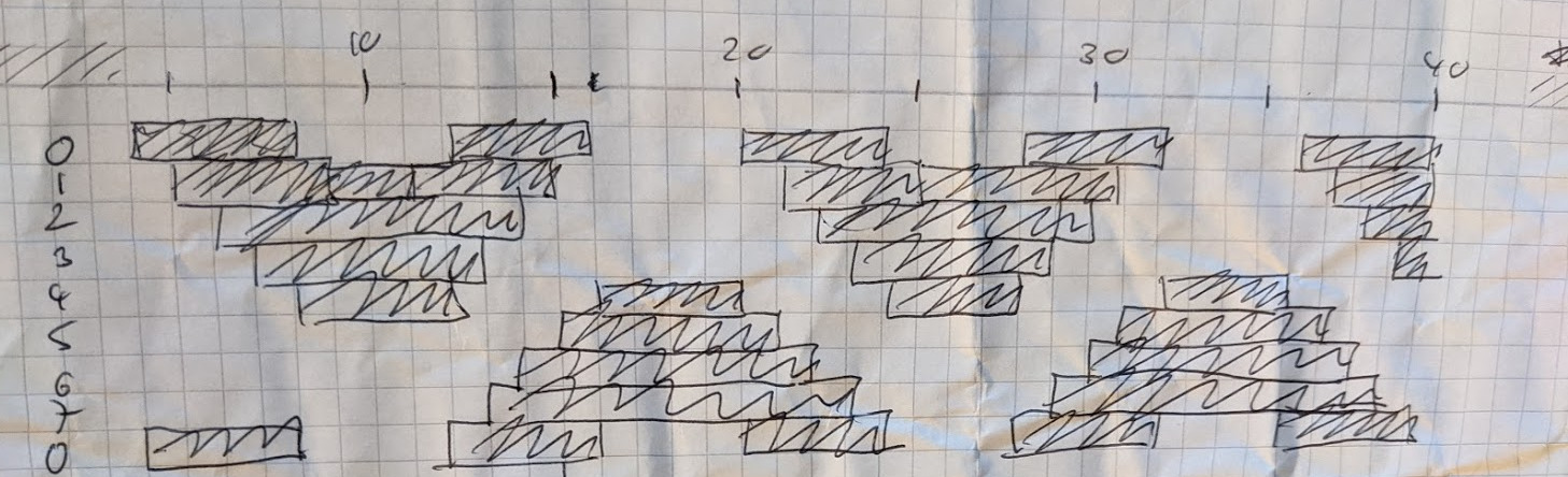
As an illustration, here's how we designed the plasma effect:
The code
In a 1541tro, the CPU has to do everything: Video signal generation, sound generation, disk reading and decoding. There are no sound chips or video chips to help with that. The only other workers on the board are the two 6522 I/O chips, which generate the square waves that make up the music.
What do we have to do? We're bitbanging the S-Video signal, so at every horizontal line of the screen, we have to generate an "HSYNC" pulse and put some "pixels" on the screen. We also have to generate the sound. It has proven useful to do that at the same time, since it actually involves the same I/O registers.
This is our TODO list for every raster line:
- Pull CLK (and DATA) low for at least 5μs.
- Take the output of the rectangle wave function generated by the first 6522, put into the low bit of the stepper motor.
- Toggle DATA between high and low, for graphic output.
Note that most emulators are blissfully unaware that you even can read out the rectangle wave from a 6522. It took us some experimentation with a 6522 on a breadboard:
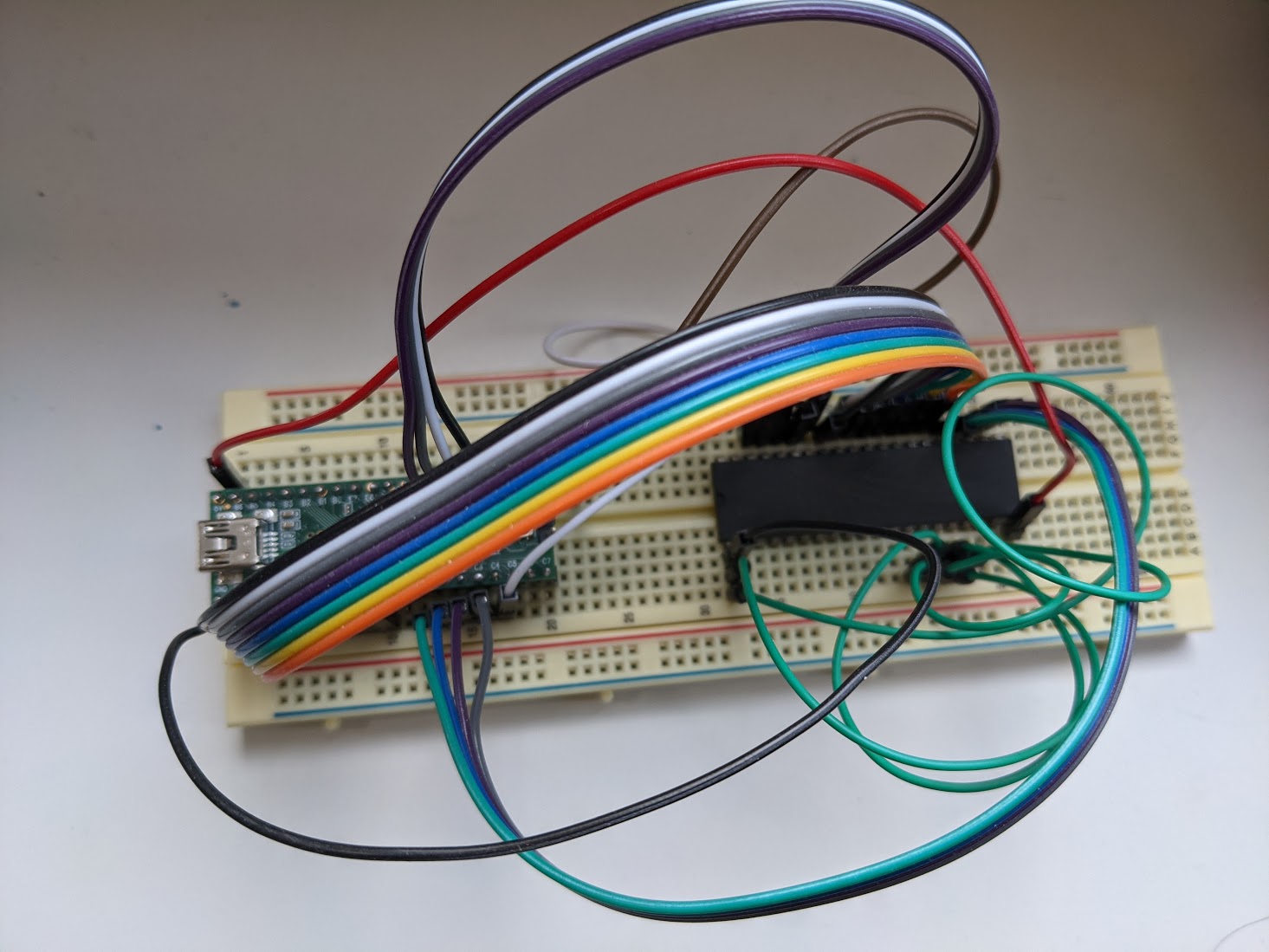
Turns out this is actually possible.
Since the rectange wave is on bit 7 of $1800 (port b of first 6522), and that's the same I/O port we also need to write for generating the HSYNC, we can kill two birds with one ASL:
asl $1800      // start hsync, put bit 7 (wave function) into carry
lda #BLACK     // bit pattern for CLOCK high, DATA low
sta $1800      // end hsync
lda #$04 >> 1  // 4 = motor on.
rol
sta $1c00      // generate sound
You can optimize that further. For example, if we switch from ROL to ADC to get the carry into bit 0, it's possible to find a value for A that works for both $1800 and $1c00, so you can combine the two LDAs. Some effects use this code:
asl $1800
lda #BLACK
sta $1800
adc #TRACK
sta $1c00
This is nice, but as it turns out, you get more interesting sounds out of the 1541 drive if you use two rectangle functions, combined using OR. So you have both I/O chips running timer 1 for music. (This actually provides another challenge: You don't have any timers left capable of being switched to "free-running". So the vertical timing needs to be done with a timer 2 with needs to be reset every VSYNC. But that's a story for a different day)
So now our TODO list has grown. It's now:
- Pull CLK (and DATA) low for at least 5us.
- Read the output of the rectangle wave function generated by the first 6522.
- Read the output of the rectangle wave function generated by the second 6522.
- Logical OR them, put into the low bit of the stepper motor.
- Toggle DATA between high and low, for graphic output.
It's not quite as straightforward to combine that with the HSYNC code, but after quite some experimentation, we found this:
// assume carry is set
lda $1c00  // Put 2nd wave function into bit 7 of A
rra $1800  // Start hsync. Put OR of 1st and 2nd wave function into C
lda #BLACK|$80|TRACK
rol        // Put sound into low bit. Also set carry back to 1.
sta $1800
sta $1c00
Note the use of the illegal opcode "RRA" here. It has been used before (e.g. in six sprites over FLI), but as far as we're aware, this is the first time a demo uses it on every scanline, in almost every effect. :)
Note that this code, as nice as it is, is a bit finicky to work with: The carry needs to always be 1 at the RRA start, and $1800 needs to be set to black (only on odd tracks, you can use the "black" you already have in A). In other words, this only works for effects for vertical scrollers etc. which have their graphics in the middle of the screen. It doesn't work for rasterline effects where a white color might run all the way to the right edge of the screen.
So whenever we could spare the cycles, we used the more lenient "long" version.
asl $1800      // start hsync, put bit 7 (wave function) into carry
lda #BLACK     // bit pattern for CLOCK high, DATA low
sta $1800      // end hsync
rol            // carry into bit 0
ora $1800
anc #$80
adc #$04|TRACK // Set 'motor on' bit
sta $1c00
Other variations are possible. For example, a version using ARR and CMP proved useful for the rotating checkerboard bar:
asl $1800
arr #$00
cmp $1c00
stx $1800
adc #$04|TRACK
sta $1c00
Code in Off-screen areas
The above makes us generate sound and video in the "visible" areas of the screen.
Most effects in freespin use a resolution of 412x256. We hence have 256 rasterlines of timing-sensitive render logic, and then 56 rasterlines worth of untimed branchy code, in which we don't even bother to generate horizontal syncs. (Commodore 1084 monitors are forgiving about these kind of things)
Unfortunately, sound isn't quite as forgiving: We do need to generate the current waveform even in the off screen areas. Not doing so messes with high notes, and also introduces unpleasant "click" noises throughout the piece.
So all our off-screen code is interleaved with 6522->6522 copying. We try to copy the waveform every 100-200 cycles. (In fact, our emulator triggers a warning if the stepper motor isn't exercised for 200 cycles)
Thankfully, generating sound only uses the "A" register and can be done with:
lda $1800
// ora $1c00   // If using two timers
anc #$80
adc #$04|TRACK
sta $1c00
This also frees the carry, so this often is code we insert instead of a CLC.
In formerly tight loops, it often caused us to partly unroll the loop, so we can generate sound without excessively wasting cycles.
To demonstrate this principle, here's a code snippet from the "zigzag lines" effect (right after "freespin - the first 1541tro" is finished scrolling through):
fill_stack:
    // generate sound
    lda $1800
    ora $1c00
    anc #$80
    adc #$04|TRACK
    sta $1c00

    // generate pattern
    lda zigzag2, y
    adc zigzag2, x
    sta $0104+42, x
    iny
    lda zigzag2, y
    adc zigzag2, x
    sta $0102+42, x
    iny
    lda zigzag2, y
    adc zigzag2, x
    sta $0100+42, x

    iny
    txa
    axs #$06
    bcs fill_stack
Unfortunately, a single sound "invocation" is 10-13 bytes, so we sometimes needed to put the code into a subroutine, swallowing the pill on the extra cycles. Balancing the memory requirements (remember: only 1.7k!) with the small amount of off-screen time (56 rasterlines) was what we spent most of our time on, when polishing the demo.